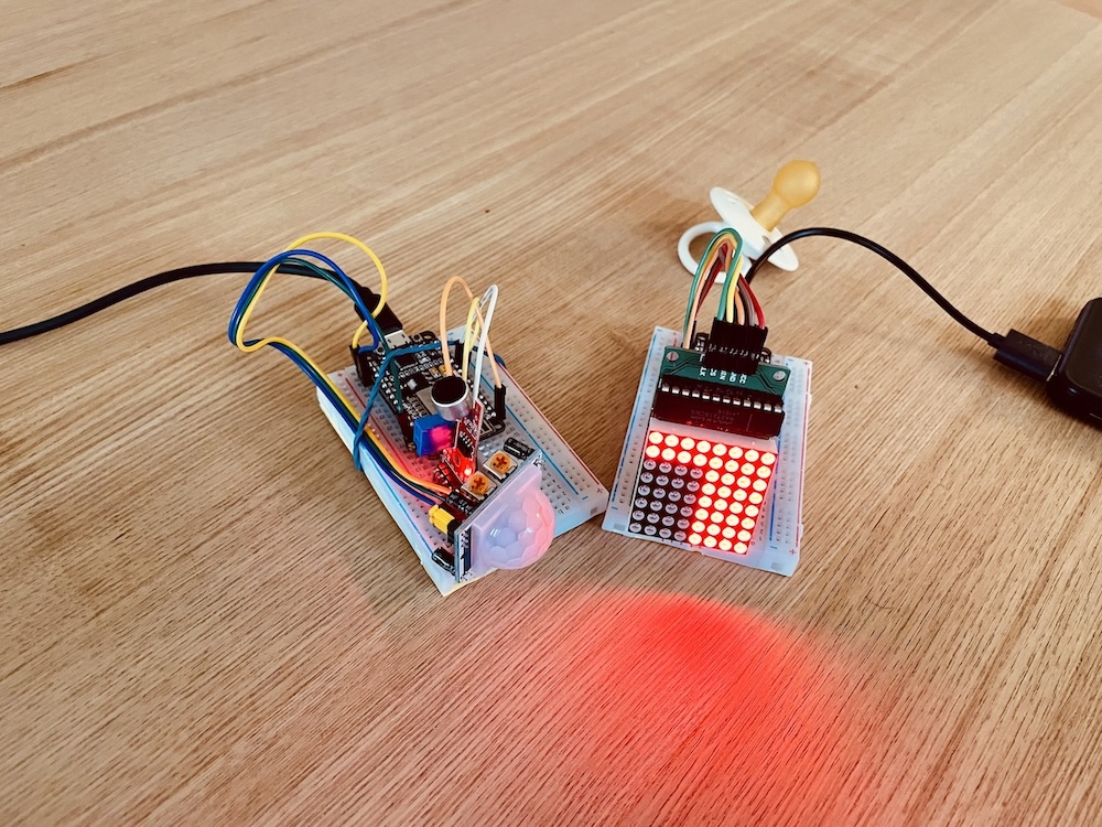
This project revolves around monitoring babies’ and young children’s sleep: You’ll build a baby monitor consisting of two ESP8266 microcontrollers connected via ESP-NOW. On the first microcontroller, you’ll connect a PIR sensor to detect motion and a sound sensor to measure noise levels.
The data is sent to a second ESP8266, which is connected to an LED matrix display. On this display, you can monitor the current noise level in the bedroom. Additionally, the display lights up when motion is detected.
You place the ESP8266 with the sensors next to the child’s bed, and the one with the display wherever you are. This way, you always have a view of what’s happening in the bedroom.
Tune in to our Google-powered podcast episode where we dive into creating this DIY baby monitor using ESP8266 microcontrollers:
With this project, you’ll learn how to:
- Connect a PIR sensor and a sound sensor to the ESP8266
- Use an LED matrix display
- Connect two ESP8266 devices using ESP-NOW
Components you’ll need:
- 2x NodeMCU ESP8266
- 1x PIR motion sensor
- 1x KY-037 or KY-038 sound sensor
- 1x 8×8 LED matrix with MAX7219 driver
- Cables and 2 breadboards
- Optional: 1 or 2 power banks for operation
The Receiver of the Baby Monitor
Let’s start with the part of the baby monitor where you can read what’s happening in the bedroom or nursery. For this, you’ll use an 8×8 LED matrix display. On one side of the display, you’ll create a kind of equalizer that shows you the measured noise level. The other side lights up red as soon as motion is detected and transmitted by the sender.
Connect the matrix display to the ESP8266 as follows:
| Display | ESP8266 |
| GND | GND |
| VCC | 3.3V |
| DIN | D5 |
| CLD | D6 |
| CS | D7 |
Next, you need to find out the MAC address of the ESP8266 to use ESP-NOW for communication between the sender and receiver. MAC stands for Media Access Control and is a unique address for identifying a device in a network.
To find this address, you can upload the following small sketch to the receiver and read the MAC address in the Serial Monitor:
#include <ESP8266WiFi.h>

void setup() {
  Serial.begin(115200);
  WiFi.mode(WIFI_STA);
  Serial.println(WiFi.macAddress());
}

void loop() {}
___STEADY_PAYWALL___
Your address might look something like this: EC:FA:BC:6E:EE:F4
You’ll need this address in the sender’s sketch to display the measurement data on the matrix display. But first, here’s the actual sketch that receives the volume and motion data and visualizes it:
//ESP-8266 Baby Monitor - Receiver
//https://en.https://en.polluxlabs.net/wp-content/uploads/2020/02/ESP8266-Webserver-small.jpg.net

#include <ESP8266WiFi.h>
#include <espnow.h>
#include <LedControl.h>

// Pins des Displays
const int DIN_PIN = D5;
const int CLK_PIN = D6;
const int CS_PIN = D7;

// LED Matrix Setup
LedControl lc = LedControl(DIN_PIN, CLK_PIN, CS_PIN, 1);

// Structure of received data
struct SensorData {
  bool motionDetected;
  int noiseLevel;
};

void setup() {
  Serial.begin(115200);

  // Initialize LED matrix
  lc.shutdown(0, false);
  lc.setIntensity(0, 8);  // Brightness (0-15)
  lc.clearDisplay(0);

  // Initialize ESP-NOW
  WiFi.mode(WIFI_STA);
  if (esp_now_init() != 0) {
    Serial.println("Error initializing ESP-NOW");
    return;
  }

  // Function for received data
  esp_now_register_recv_cb(onDataReceived);
}

void loop() {
  // Empty
}

void onDataReceived(uint8_t *mac, uint8_t *incomingData, uint8_t len) {
  SensorData data;
  memcpy(&data, incomingData, sizeof(data));

  // Update Display
  updateLEDMatrix(data.motionDetected, data.noiseLevel);

  // Print received data in the Serial Monitor
  Serial.print("Motion: ");
  Serial.print(data.motionDetected);
  Serial.print(" | Noise: ");
  Serial.println(data.noiseLevel);
}

void updateLEDMatrix(bool motionDetected, int noiseLevel) {
  lc.clearDisplay(0);

  // Show movement
  if (motionDetected) {
    for (int row = 0; row < 4; row++) {
      for (int col = 0; col < 8; col++) {
        lc.setLed(0, row, col, true);
      }
    }
  }

  // Show volume
  int noiseLEDs = map(noiseLevel, 150, 300, 0, 8);
  for (int row = 4; row < 8; row++) {
    for (int col = 0; col < noiseLEDs; col++) {
      lc.setLed(0, row, col, true);
    }
  }
}
Explanation of the Sketch
Let’s take a closer look at the code in this sketch.
Libraries and Definitions
#include <ESP8266WiFi.h>
#include <espnow.h>
#include <LedControl.h>

const int DIN_PIN = D5;
const int CLK_PIN = D6;
const int CS_PIN = D7;

LedControl lc = LedControl(DIN_PIN, CLK_PIN, CS_PIN, 1);

struct SensorData {
  bool motionDetected;
  int noiseLevel;
};
The code uses the ESP8266WiFi and espnow libraries for wireless communication and the LedControl library for controlling the LED matrix. You’ll probably need to install the latter through the library manager.
The pins for the LED matrix are defined (DIN, CLK, CS) and a LedControl object is created to control the LED matrix. Lastly, you create a structure to store the received data in variables.
Setup Function
void setup() {
  Serial.begin(115200);

  lc.shutdown(0, false);
  lc.setIntensity(0, 8);
  lc.clearDisplay(0);

  WiFi.mode(WIFI_STA);
  if (esp_now_init() != 0) {
    Serial.println("Error initializing ESP-NOW");
    return;
  }

  esp_now_register_recv_cb(onDataReceived);
}- Serial communication is initialized.
- The LED matrix is turned on, brightness is set to 8 (out of 15), and the display is cleared.
- The ESP8266 is set to Station mode.
- ESP-NOW is initialized and an error is reported if initialization fails.
- The onDataReceived function is registered as a callback for received data.
Main Loop
void loop() {
}
The sketch’s loop remains empty as data processing occurs in the following function.
Data Receive Callback
void onDataReceived(uint8_t *mac, uint8_t *incomingData, uint8_t len) {
  SensorData data;
  memcpy(&data, incomingData, sizeof(data));

  updateLEDMatrix(data.motionDetected, data.noiseLevel);

  Serial.print("Motion: ");
  Serial.print(data.motionDetected);
  Serial.print(" | Noise: ");
  Serial.println(data.noiseLevel);
}- This function is called when data is received.
- The received data is copied into the SensorData structure.
- The LED matrix is updated with the received data.
- The received data is output to the Serial Monitor.
LED Matrix Update
void updateLEDMatrix(bool motionDetected, int noiseLevel) {
  lc.clearDisplay(0);

  if (motionDetected) {
    for (int row = 0; row < 4; row++) {
      for (int col = 0; col < 8; col++) {
        lc.setLed(0, row, col, true);
      }
    }
  }

  int noiseLEDs = map(noiseLevel, 150, 300, 0, 8);
  for (int row = 4; row < 8; row++) {
    for (int col = 0; col < noiseLEDs; col++) {
      lc.setLed(0, row, col, true);
    }
  }
}
This function updates the LED matrix based on the received sensor data.
- First, the display is cleared.
- If motion is detected, the top 4 rows of the matrix are fully lit.
- The noise level is mapped to the bottom 4 rows. The number of lit LEDs depends on the noise level, with values between 150 and 300 mapped to 0 to 8 LEDs.
This code continuously receives data from a sender, processes it, and displays it visually on an LED matrix.
The map function is important here, which in the above code “maps” values between 150 and 300 to the eight rows of the display. These are values that you set directly on the sound sensor on one hand and must determine experimentally on the other. So how high does the sensor value go with a certain noise level? Ideally, all 8 rows should light up when a maximum “usual” volume is reached, for example through screaming.
The Sender of the Baby Monitor
Now let’s move on to the second part of the baby monitor – the sender with the sound and motion detectors. This ESP8266 determines whether the child is moving or even crying or screaming. A PIR sensor is suitable for this, as it detects movement in the dark and its sensitivity can be adjusted so that not every turn in bed triggers an alert. Additionally, a simple sound sensor is used to represent the volume in the room as a number between 0 and 1023.
First, connect both sensors to the ESP8266 as follows:

You’ll read the analog output from the sound sensor, which means you must use the analog input A0 of the ESP8266. You have free choice for the digital pin – in the following, it’s pin D1.
Let’s move straight to the sketch:
//ESP-8266 Baby Monitor - Sender
//https://en.https://en.polluxlabs.net/wp-content/uploads/2020/02/ESP8266-Webserver-small.jpg.net

#include <ESP8266WiFi.h>
#include <espnow.h>

const int PIR_PIN = D1;
const int NOISE_PIN = A0;

//MAC-Address of receiver
uint8_t receiverAddress[] = {0xEC, 0xFA, 0xBC, 0x6E, 0xEE, 0xF4};

struct SensorData {
  bool motionDetected;
  int noiseLevel;
};

void OnDataSent(uint8_t *mac_addr, uint8_t sendStatus) {
  Serial.print("Last Packet Send Status: ");
  if (sendStatus == 0){
    Serial.println("Delivery success");
  }
  else{
    Serial.println("Delivery fail");
  }
}

void setup() {
  Serial.begin(115200);
  pinMode(PIR_PIN, INPUT);
  pinMode(NOISE_PIN, INPUT);

  WiFi.mode(WIFI_STA);
  WiFi.disconnect();

  if (esp_now_init() != 0) {
    Serial.println("Error initializing ESP-NOW");
    return;
  }

  esp_now_set_self_role(ESP_NOW_ROLE_CONTROLLER);
  esp_now_register_send_cb(OnDataSent);

  esp_now_add_peer(receiverAddress, ESP_NOW_ROLE_SLAVE, 1, NULL, 0);

  Serial.println("Sender initialized");
}

void loop() {
  SensorData data;

  data.motionDetected = digitalRead(PIR_PIN);
  data.noiseLevel = analogRead(NOISE_PIN);

  esp_now_send(receiverAddress, (uint8_t *) &data, sizeof(data));

  Serial.print("Sending - Motion: ");
  Serial.print(data.motionDetected);
  Serial.print(" | Noise: ");
  Serial.println(data.noiseLevel);

  delay(200);
}
Much of this sketch should already be familiar to you from the receiver’s sketch. In the loop, you capture the sensor data and send it via ESP-NOW to the receiver’s ESP8266. At the very end, you set a delay to determine how often the data is measured – here, a value of 200 milliseconds is practical. Of course, you can experiment with this.
Adjusting the Sound Sensor
There’s one more thing you need to do with the baby monitor’s hardware and update the receiver’s sketch accordingly. On the sound sensor, you’ll find a small screw that allows you to set what value should represent silence. Upload the above sketch to your ESP8266 and observe the measured values in the Serial Monitor. Now turn the screw until the values settle slightly below 200.
Now make a louder noise at some distance (for example, at the volume of a crying child) and observe how the measured values behave. This upper value will be the value at which all 8 rows of the matrix display should light up. Now adjust the number 300 in the receiver sketch accordingly:
int noiseLEDs = map(noiseLevel, 150, 300, 0, 8);And that’s it. Power both ESP8266s, for example using power banks. They should then establish a connection with each other and the display should light up.
If not, double-check the MAC address you entered. Does it match that of the receiver?
Further Ideas for Your Baby Monitor
Besides the display, you could of course use other methods to inform yourself. This could be a simple piezo buzzer, or even a WhatsApp message to your smartphone.
