Sometimes, even a small Arduino is too large for your project. Maybe you only need a few pins, want to use as little power as possible, or don’t have enough physical space. In these cases, the ATtiny85 might be just what you need.
ATtiny processors come in various versions, but the ATtiny85 is the most well-known and commonly used. This guide will introduce you to it. While setting up and programming this chip isn’t as straightforward as working with an Arduino, it’s not difficult either!
ATtiny85 Basics
You’ll notice a notch on one corner of your ATtiny85. Orient the chip so that the notch is in the top-left position. The pin numbers are assigned counterclockwise, starting with Pin 1 next to the notch.
However, the pin numbers on the chip don’t match the ones you’ll use in your Arduino sketch. The table below shows the mapping:
| Pin on ATtiny85 | Function | Pin in Sketch |
|---|---|---|
| 1 | Reset | |
| 2 | 3 | |
| 3 | 4 | |
| 4 | GND | |
| 5 | 0 | |
| 6 | 1 | |
| 7 | 2 | |
| 8 | VCC |
For example, to control an LED connected to Pin 3 on the ATtiny85, define this pin in your sketch as follows:
pinMode(4, OUTPUT);Preparing the Arduino IDE
Before you begin, you need to teach the Arduino IDE how to communicate with the ATtiny85.
- Open the Preferences menu.
- Locate the Additional Boards Manager URLs field, and paste the following URL into it:
https://raw.githubusercontent.com/damellis/attiny/ide-1.6.x-boards-manager/package_damellis_attiny_index.jsonThen click OK to save. - Open the Boards Manager (under Tools > Board > Boards Manager). Search for
attinyand install the package created by David A. Mellis.
Now you’re ready to connect your ATtiny85 to an Arduino and program it.
Connecting the ATtiny85 to the Arduino
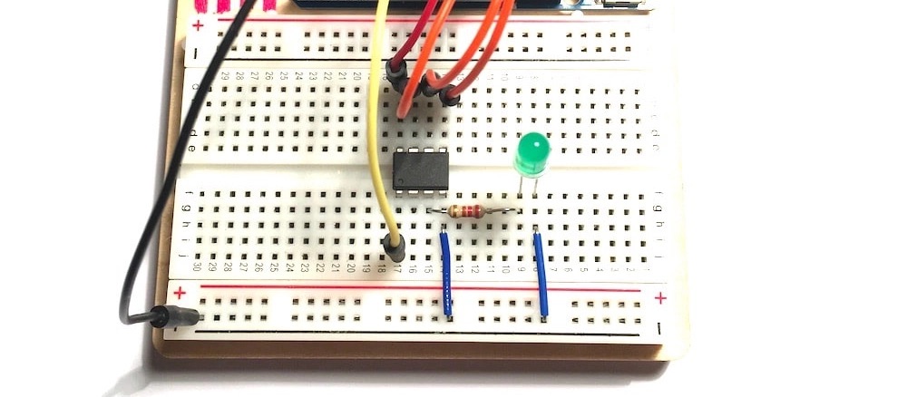
Grab a breadboard and place the ATtiny85 across the middle gap. For the first sketch, you’ll make an LED blink, so include this basic circuit on the breadboard. You’ll need:
- A capacitor (e.g., 100 µF)
- An LED
- A 220Ω resistor
- Some wires
___STEADY_PAYWALL___
Here’s the schematic layout:

As you can see, it’s a simple setup. Besides the power connections (Pin 8 to VCC, Pin 4 to GND, Pin 1 for Reset), you’ll also use Pins 5–7 to program the ATtiny85. Connect them to the Arduino’s digital Pins 11–13.
Connect an LED (with a 220Ω resistor) to Pin 3 of the ATtiny85, and tie it to ground. You’ll use this LED to test if the Arduino successfully programs the ATtiny85.
Note: Do not connect the capacitor between GND and Reset on the Arduino yet. This will be needed later.
Configuring the Arduino as a Programmer
- Load the ArduinoISP sketch onto your Arduino (found in File > Examples > 11.ArduinoISP).
- Make sure the capacitor is not connected yet, or the sketch won’t upload.
Programming the ATtiny85
Once the Arduino is ready, proceed to program the ATtiny85:
- Insert the capacitor into the Arduino’s GND and Reset (RES) pins. Ensure correct orientation: the negative side of the capacitor connects to GND.
- In the Arduino IDE, configure the following settings:
- Board: Select ATtiny25/45/85.
- Processor: Choose ATtiny85.
- Clock: Use Internal 1MHz.
- Programmer: Select Arduino as ISP.
Your settings should now resemble the screenshot below:

Uploading the Sketch
Here’s the basic code to blink an LED:
int ledPin = 4;

void setup() {
  pinMode(ledPin, OUTPUT);
}

void loop() {
  digitalWrite(ledPin, HIGH);
  delay(500);
  digitalWrite(ledPin, LOW);
  delay(500);
}
Important: Remember the pin mapping differences. Even though your LED is physically connected to Pin 3 on the ATtiny85, you control it as 4 in the sketch.
Upload the sketch. If everything is set up correctly, your LED should blink on and off every half second.
