In the previous part, you learned about the MQTT broker and how to set it up with Mosquitto on a Raspberry Pi. Now, it’s time to establish communication between devices. In this tutorial, you will learn how to send data from an ESP8266 to the broker and how another ESP8266 can subscribe to this data and react accordingly. Specifically, you will send the current light intensity, and when it gets dark, a light will turn on elsewhere.
Required Components
For this lesson, you will need the following components:
- 2x ESP8266 module
- 1x Light sensor plus 10kΩ resistor
- 1x LED with a suitable series resistor
- Breadboards and jumper wires
To use MQTT with the ESP8266, you will utilize the PubSubClient library by Nick O’Leary, which is optimized for use with the Arduino IDE and ESP8266.
Installing the PubSubClient Library
- Open the Arduino IDE.
- Navigate to Sketch > Include Library > Manage Libraries (or click the corresponding button in the left menu).
- Search for PubSubClient and install the latest version.

Sending Data to the MQTT Broker
Let’s create a simple sketch that establishes a connection to the MQTT broker and publishes a message.
//Send messages to the MQTT broker

#include <ESP8266WiFi.h>
#include <PubSubClient.h>

const char* ssid = "YOUR_WIFI_SSID";
const char* password = "YOUR_WIFI_PASSWORD";
const char* mqtt_server = "BROKER_IP_ADDRESS";

WiFiClient espClient;
PubSubClient client(espClient);

void setup() {
  Serial.begin(115200);
  setup_wifi();
  client.setServer(mqtt_server, 1883);
}

void setup_wifi() {
  delay(10);
  Serial.println();
  Serial.print("Connecting to ");
  Serial.println(ssid);

  WiFi.mode(WIFI_STA);
  WiFi.begin(ssid, password);

  while (WiFi.status() != WL_CONNECTED) {
    delay(500);
    Serial.print(".");
  }

  Serial.println("\nWiFi connected");
  Serial.println("IP Address: ");
  Serial.println(WiFi.localIP());
}

void reconnect() {
  while (!client.connected()) {
    Serial.print("Connecting to MQTT...");
    if (client.connect("ESP8266Client")) {
      Serial.println("connected");
    } else {
      Serial.print("Failed, rc=");
      Serial.print(client.state());
      Serial.println(" Trying again in 5 seconds");
      delay(5000);
    }
  }
}

void loop() {
  if (!client.connected()) {
    reconnect();
  }
  client.loop();

  client.publish("esp8266/test", "Hello from ESP8266!");
  delay(5000);
}
Replace YOUR_WIFI_SSID, YOUR_WIFI_PASSWORD, and BROKER_IP_ADDRESS with your actual values. If you don’t know the IP address of your Raspberry Pi (where the broker is running), enter the following command in the terminal:
hostname -IThis will display the IP address, e.g., 192.168.0.143.
The sketch connects to Wi-Fi and the MQTT broker. In the loop() function, a message is sent to the topic esp8266/test every 5 seconds.
Upload the sketch to your ESP8266 and open the Serial Monitor. You should see the ESP8266 establishing a connection and sending messages.
On the Raspberry Pi, you can receive these messages using mosquitto_sub. Open a new terminal window (while Mosquitto is running) and enter:
___STEADY_PAYWALL___
mosquitto_sub -t esp8266/testReceiving Data from the MQTT Broker
Now, let’s make an ESP8266 react to incoming MQTT messages. You will connect an LED to your ESP8266 and control it remotely via MQTT.
Connecting the LED
Wire the LED to your ESP8266 as follows:
- LED Anode (+) → Connect to D5 (GPIO14) via a resistor
- LED Cathode (-) → Connect to GND

Sketch for Receiving Messages
//Receive messages

#include <ESP8266WiFi.h>
#include <PubSubClient.h>

const char* ssid = "YOUR_WIFI_SSID";
const char* password = "YOUR_WIFI_PASSWORD";
const char* mqtt_server = "BROKER_IP_ADDRESS";

WiFiClient espClient;
PubSubClient client(espClient);

const int ledPin = D5;

void setup() {
  pinMode(ledPin, OUTPUT);
  Serial.begin(115200);
  setup_wifi();
  client.setServer(mqtt_server, 1883);
  client.setCallback(callback);
}

void callback(char* topic, byte* payload, unsigned int length) {
  Serial.print("Message received [");
  Serial.print(topic);
  Serial.print("] ");
  for (int i = 0; i < length; i++) {
    Serial.print((char)payload[i]);
  }
  Serial.println();

  if ((char)payload[0] == '1') {
    digitalWrite(ledPin, HIGH);
  } else {
    digitalWrite(ledPin, LOW);
  }
}

void reconnect() {
  while (!client.connected()) {
    Serial.print("Connecting to MQTT...");
    if (client.connect("ESP8266Client_Receiver")) {
      Serial.println("connected");
      client.subscribe("esp8266/led");
    } else {
      Serial.print("Failed, rc=");
      Serial.print(client.state());
      Serial.println(" Trying again in 5 seconds");
      delay(5000);
    }
  }
}

void loop() {
  if (!client.connected()) {
    reconnect();
  }
  client.loop();
}
To test this setup via the terminal, use the following commands (replace BROKER_IP_ADDRESS with the actual IP of your Raspberry Pi):
mosquitto_pub -h BROKER_IP_ADDRESS -t "esp8266/led" -m "1"  # Turn LED on
mosquitto_pub -h BROKER_IP_ADDRESS -t "esp8266/led" -m "0"  # Turn LED off
Communication Between Two ESP8266
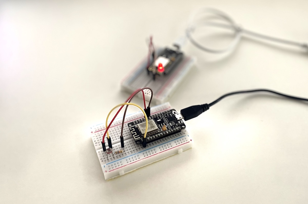
So far, you have used the terminal to operate the MQTT broker, sending and receiving messages from an ESP8266. However, the broker is supposed to work in the background, acting like a mail carrier that you don’t really notice. Now, two ESP8266 boards will communicate with each other:
The first ESP8266 is equipped with a light sensor that measures light intensity. If the light falls below a certain threshold, it sends a message to the broker. The second ESP8266 is subscribed to these messages and turns on an LED when needed.
You have already installed the LED. Now, connect the light sensor to the other ESP8266 as follows:

Sketch for the Sender
For the ESP8266 that sends messages with the connected light sensor, use the following sketch:
// Send Light Intensity

#include <ESP8266WiFi.h>
#include <PubSubClient.h>

const char* ssid = "YOUR_WIFI_SSID";
const char* password = "YOUR_WIFI_PASSWORD";
const char* mqtt_server = "BROKER_IP_ADDRESS";

WiFiClient espClient;
PubSubClient client(espClient);

const int lightSensorPin = A0;
const int lightThreshold = 500;

void setup() {
  Serial.begin(115200);
  setup_wifi();
  client.setServer(mqtt_server, 1883);
}

void setup_wifi() {
  delay(10);
  Serial.println();
  Serial.print("Connecting to ");
  Serial.println(ssid);

  WiFi.mode(WIFI_STA);
  WiFi.begin(ssid, password);

  while (WiFi.status() != WL_CONNECTED) {
    delay(500);
    Serial.print(".");
  }

  Serial.println("\nWiFi connected");
  Serial.println("IP Address: ");
  Serial.println(WiFi.localIP());
}

void reconnect() {
  while (!client.connected()) {
    Serial.print("Connecting to MQTT...");
    if (client.connect("ESP8266Client_Publisher")) {
      Serial.println("connected");
    } else {
      Serial.print("Failed, rc=");
      Serial.print(client.state());
      Serial.println(" Retrying in 5 seconds");
      delay(5000);
    }
  }
}

void loop() {
  if (client.connected()) {
    client.loop();

    int lightValue = analogRead(lightSensorPin);
    Serial.print("Light value: ");
    Serial.println(lightValue);

    if (lightValue < lightThreshold) {
      client.publish("esp8266/light", "1");  // Turn LED on
      Serial.println("MQTT Message Sent: 1");
    } else {
      client.publish("esp8266/light", "0");  // Turn LED off
      Serial.println("MQTT Message Sent: 0");
    }

    delay(5000);
  } else {
    reconnect();
  }
}
At the top of the sketch, besides the usual WiFi and broker credentials, you can set the lightThreshold constant to determine the sensor’s trigger value. After uploading the sketch, you can see the current value in the Serial Monitor. Use this information to define a suitable threshold for your application.
The sender measures the light intensity every 5 seconds and then sends the corresponding message via MQTT.
Sketch for the Receiver
Now, your second ESP8266 with the connected LED should react to these messages. Upload the following sketch:
// Receive Light Intensity

#include <ESP8266WiFi.h>
#include <PubSubClient.h>

const char* ssid = "YOUR_WIFI_SSID";
const char* password = "YOUR_WIFI_PASSWORD";
const char* mqtt_server = "BROKER_IP_ADDRESS";

WiFiClient espClient;
PubSubClient client(espClient);

const int ledPin = D5;

void setup() {
  pinMode(ledPin, OUTPUT);
  Serial.begin(115200);
  setup_wifi();
  client.setServer(mqtt_server, 1883);
  client.setCallback(callback);
}

void setup_wifi() {
  delay(10);
  Serial.println();
  Serial.print("Connecting to ");
  Serial.println(ssid);

  WiFi.mode(WIFI_STA);
  WiFi.begin(ssid, password);

  while (WiFi.status() != WL_CONNECTED) {
    delay(500);
    Serial.print(".");
  }

  Serial.println("\nWiFi connected");
  Serial.println("IP Address: ");
  Serial.println(WiFi.localIP());
}

void callback(char* topic, byte* payload, unsigned int length) {
  Serial.print("Message received [");
  Serial.print(topic);
  Serial.print("] ");
  for (int i = 0; i < length; i++) {
    Serial.print((char)payload[i]);
  }
  Serial.println();

  if ((char)payload[0] == '1') {
    digitalWrite(ledPin, HIGH);  // Turn LED on
  } else {
    digitalWrite(ledPin, LOW);  // Turn LED off
  }
}

void reconnect() {
  while (!client.connected()) {
    Serial.print("Connecting to MQTT...");
    if (client.connect("ESP8266Client_Receiver")) {
      Serial.println("connected");
      client.subscribe("esp8266/light");
    } else {
      Serial.print("Failed, rc=");
      Serial.print(client.state());
      Serial.println(" Retrying in 5 seconds");
      delay(5000);
    }
  }
}

void loop() {
  if (client.connected()) {
    client.loop();
  } else {
    reconnect();
  }
}
This sketch is almost identical to the one where you controlled the LED via the terminal. However, there is one crucial detail when two ESP8266 devices communicate via the MQTT broker:
They must have different client names.
The name with which your ESP8266 registers with the broker is defined in the following function (near the bottom of the sketch):
client.connect("ESP8266Client_Receiver")
That’s it! This is all you need for basic communication between two ESP8266 devices. Now, test all three devices (broker, sender, and receiver) and check if the LED turns on when the light goes out.
