A potentiometer (or “pot”) is a practical component when you want to control the “strength” of something. You certainly know them from everyday life, perhaps without realizing that they’re potentiometers. The volume control on your amplifier, the knobs on your electric guitar – all potentiometers.
Let’s take a quick look at how a potentiometer works.
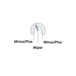
Most potentiometers have three connections: two for minus/plus and one for the wiper (also called slider). With it, you can continuously adjust a resistance value by sliding the wiper over a fixed resistor. Depending on the position of the wiper, the current flow in the material changes – and with it the volume of the music or the brightness of the light.
Usually it doesn’t matter which ends you connect plus and minus to – in which direction the current flows. However, if you swap them, you’ll flip the measurement results.
Connection to the Arduino
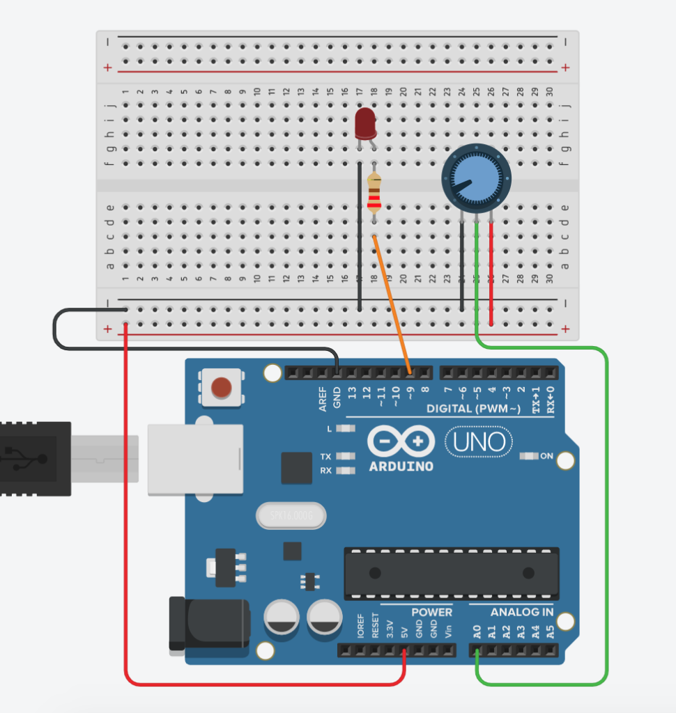
Now it’s time to add a potentiometer to your breadboard. Use the following diagram as a guide for your setup.
___STEADY_PAYWALL___
Once you’ve wired everything up, you can upload a small test to your Arduino. You’ll find the sketch for this in the downloads for this lesson.
With this sketch, you can check if your potentiometer is working by outputting its values to the Serial Monitor. The integrated analog-to-digital converter of your Arduino assigns a value from 0 to 1023 to each position of the potentiometer.
Try swapping plus and minus. The values in the Serial Monitor should now increase counterclockwise instead of clockwise.
