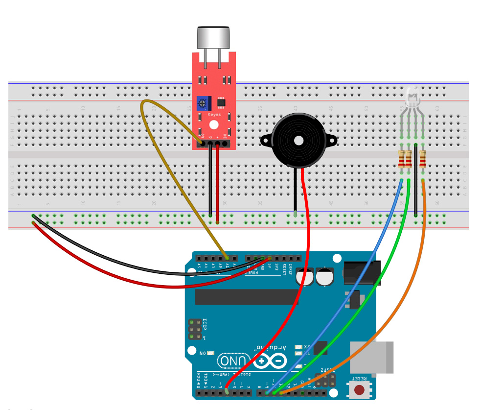
In this lesson, you’ll build the alarm system step by step. You’ve already installed the sound sensor. If you’ve removed it from your breadboard in the meantime, that’s not a problem. You can find the connections in the sketch below. However, for the alarm system, you only need the analog output (AO) of the sensor. You can omit the cable on the digital output.
Connect the active piezo
You’ve already encountered the passive piezo buzzer with the music box and theremin. As you know, you can generate different tones with it. Not so with the active piezo: this component can only generate a single tone – and does so as soon as it receives power. However, this is completely sufficient for an alarm system.
If you’re not sure whether your piezo is active or passive, simply apply 5V voltage directly from your Arduino. Does a tone sound? Then it’s the active piezo that you need for this project.
The connection is very simple. Connect the short leg of the piezo buzzer to minus (ground) and the long leg to digital pin 4 on your Arduino. When the sound sensor triggers an alarm later, you’ll send current to the piezo through this pin, which will then start to beep.
___STEADY_PAYWALL___
The RGB LED connection
Connecting this LED is a bit more complex. It has a total of 4 legs: a cathode, which you connect to minus (ground), and three anodes – one each for the colors red, green, and blue. As you’re used to with “regular” LEDs, you also need to install a 220Ω resistor here – one for each anode.
Connect the three anodes to digital pins 9, 10, and 11. These three pins have pulse width modulation (PWM), which you’ve already learned about when controlling the brightness of a simple LED.
The color channels and Arduino pins shown above may not match up depending on the type of LED you have. In the example below, the red color channel is to the right of the cathode, which might be different for your LED. However, you can easily figure this out and fix it when you switch the color of the light later: simply adjust the variables in the sketch and write the correct pin behind the color channel:
int ledRed = 10;
int ledGreen = 9;
int ledBlue = 8;
If you’ve set up and wired everything as shown in the sketch above, you can continue with the code in the next lesson.
