The first Arduino microcontroller is also the most well-known: the Arduino UNO. Its development began in 2003 in Italy. A group of students developed it with the goal of creating an affordable and easily programmable microcontroller for hobbyists and students.
And they succeeded. In 2005, the Arduino UNO was born – and it didn’t take long before it won the hearts of makers around the globe.

The first Arduino prototype The first Arduino prototype, Photo: Philliptorrone, Wikipedia Even today, for many people it’s still the first microcontroller they hold in their hands. It’s affordable in its original form and even more affordable as a clone. It also offers convenience when building projects and programming. Let’s take a look at its most important features and components together.
The Brain: ATmega328P
No microcontroller without a microchip. For the Arduino UNO, this is the ATmega328P, which sits centrally in a socket on the Arduino board.
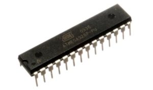
ATmega328P Microchip ATmega328P Your uploaded programs land on this chip – for which you have 32KB available. Measured against modern storage media, that sounds like nothing, but you’ll see that you can already do an incredible amount with it.
If you take a closer look at the ATmega328P, you’ll see that it has 28 “legs” – called pins. You can program 23 of these pins. When you turn your Arduino UNO over, you can see the circuit traces that lead to the sockets on the sides of the board, among other things.
So if you plug an LED into socket A5 here, you’re connecting it to the corresponding pin on the microchip.
The Most Important Pins of the Arduino UNO
Next, let’s take a look at the pins we’ll need throughout the course.
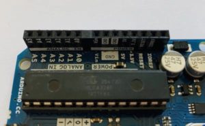
Here we first have pins that are labeled Power. The two GND pins serve as the “negative pole” or “ground.” This means you can connect the cathode (minus) of an LED here, for example, to close the circuit in which it’s located.
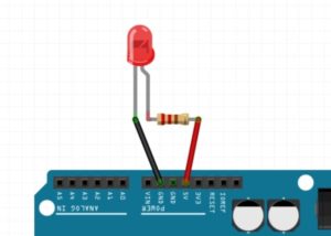
An LED on the Arduino UNO An LED on the Arduino UNO In the sketch above, you can see that the anode (plus) of the LED is connected to 5 volts via a current-limiting resistor. Its negative pole leads directly to GND. You’ll learn more about LEDs and resistors later.
This leads us directly to the two pins 5V and 3V3. Through these, you can power components – like the LED above. Depending on how much voltage (Volts) they require, you have either 5 Volts or 3.3 Volts available. Most hobby components such as servo motors, sensors, etc. require one of these two voltages.
The only pin left is VIN. You can use this to power the Arduino UNO – but we’ll take a closer look at that shortly when we talk about power supply.
The Analog Pins
First, let’s look at the analog pins A0 to A5. With these six pins, you can “measure” signals that can change continuously. In fact, these are changing voltages between 0 and 5 volts. An example is a temperature sensor that changes its output signal (i.e., the voltage) when it gets warmer or colder.
This voltage is converted in the Arduino by a so-called Analog-Digital Converter (ADC) into a corresponding number from 0 to 1023:
In the simulation above, you can see the TMP36 sensor on the Arduino UNO. By adjusting the temperature, the numbers on the right change. The analog pins are therefore useful whenever you want to measure a variable signal – and not just either a zero or a one. However, you cannot output a variable signal via the analog pins; that’s only possible via some of the digital pins – which brings us directly to the other side of the Arduino UNO.
The Digital Pins
Here you’ll find a total of 13 digital pins. However, only pins 2 to 13 are available for your projects – pins 0 and 1 are reserved for something else and cannot be programmed.
With the digital pins, you can measure and output the signals zero (off) and one (on). This means, for example, that you can turn an LED on and off via one of the pins. Or you can measure whether a button has been pressed.
Some of the digital pins are marked with a tilde (~). Through these pins, you can achieve what you might have expected from the analog pins: you can output an analog, or variable, signal. This allows you to, for example, make an LED shine with different brightness levels.
The technical term for this is Pulse Width Modulation (PWM). You will learn more about this topic in later lessons. There you’ll put PWM into practice.
Restarting the Arduino
Finally, let’s take a look at a button located on your Arduino UNO next to the USB socket: the reset button. If you want to restart your Arduino, simply press this button and its code will start over from the beginning.
And that’s it for now. You now know the most important components of your Arduino UNO that we’ll be using throughout the course.